
The Creator's Kit has various links in multiple sizes and quantities. These links can be connected using fasteners. Custom mechanisms can be created which need an axial motion from one point to another.
In these types of mechanisms, a lock nut is preferred more than a regular nut. A lock nut, also known as a self-locking nut, is a type of fastener that resists loosening when subjected to vibration or torque.
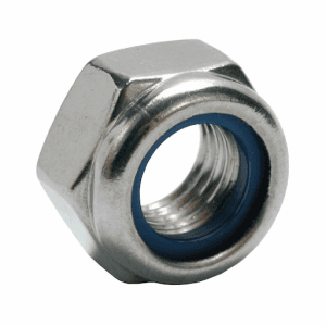
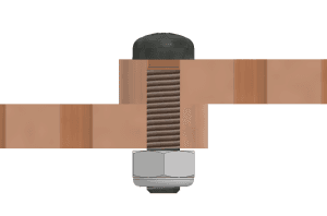
Screw the M3 lock nut onto a bolt connecting two links in the same manner as a regular nut, as illustrated in the image above. Points A and B should NOT wobble and must rotate smoothly about the axis.
Below given is the assembly of basic linkage mechanisms:
Corner Linkage Mechanism
Corner Linkage – Parts Used
Assembly Steps
Corner Linkage – Assembly Steps
- Take two strips (wooden parts) and align the end holes of each strip.
- Insert M3 Bolt (12mm) and M3 Lock Nut at the other end.
- Tighten the M3 Lock Nut and it will give you a joint for rotational motion.
Cross Linkage Mechanism
Cross Linkage – Parts Used
Assembly Steps
Cross Linkage – Assembly Steps
- Take two strips (wooden parts) and align the center holes of each strip.
- Insert M3 Bolt (12mm) and M3 Lock Nut at the other end.
- Tighten the M3 Lock Nut and it will give you a joint for rotational motion. Use the middle of the strips.
Parallel Linkage Mechanism
Parallel Linkage – Parts Used
Assembly Steps
Parallel Linkage – Assembly Steps
- Take two strips (1-9) and two strips (1-5) and align the same size strips parallelly.
- Insert M3 Bolt (12mm) and M3 Lock Nut at the four corners.
- Tighten the M3 Lock Nuts.
- This will give you a rhombus shape with a parallel linkage movement.
.webp&w=3840&q=75)
.webp&w=3840&q=75)
.webp&w=3840&q=75)
.webp&w=3840&q=75)
.webp&w=3840&q=75)